Roland KC-200 Keyboard Amp Repair

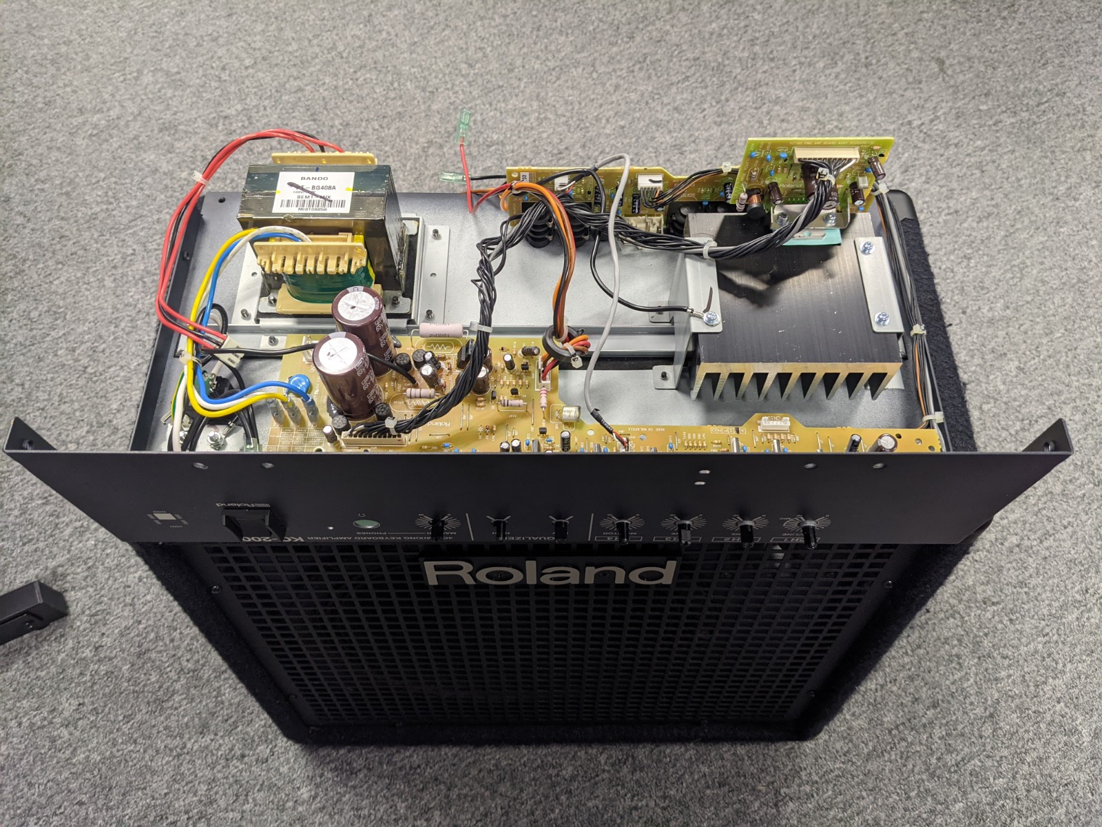
We recently had the pleasure of getting in a Roland KC-200 Keyboard Amplifier for repair. The customer was complaining about how there was no sound coming out of the speakers of the amplifier. So as always the first thing you do is check all connections and settings from the keyboard to the amplifier. I can’t tell you how many times customers have called me and the problem is not with the amplifier but with some setting on the keyboard or how they have the keyboard connected to the amplifier. Whenever that happens I am always reminded of the British TV show the IT Crowd, “Have you tried turning it off and on again.”
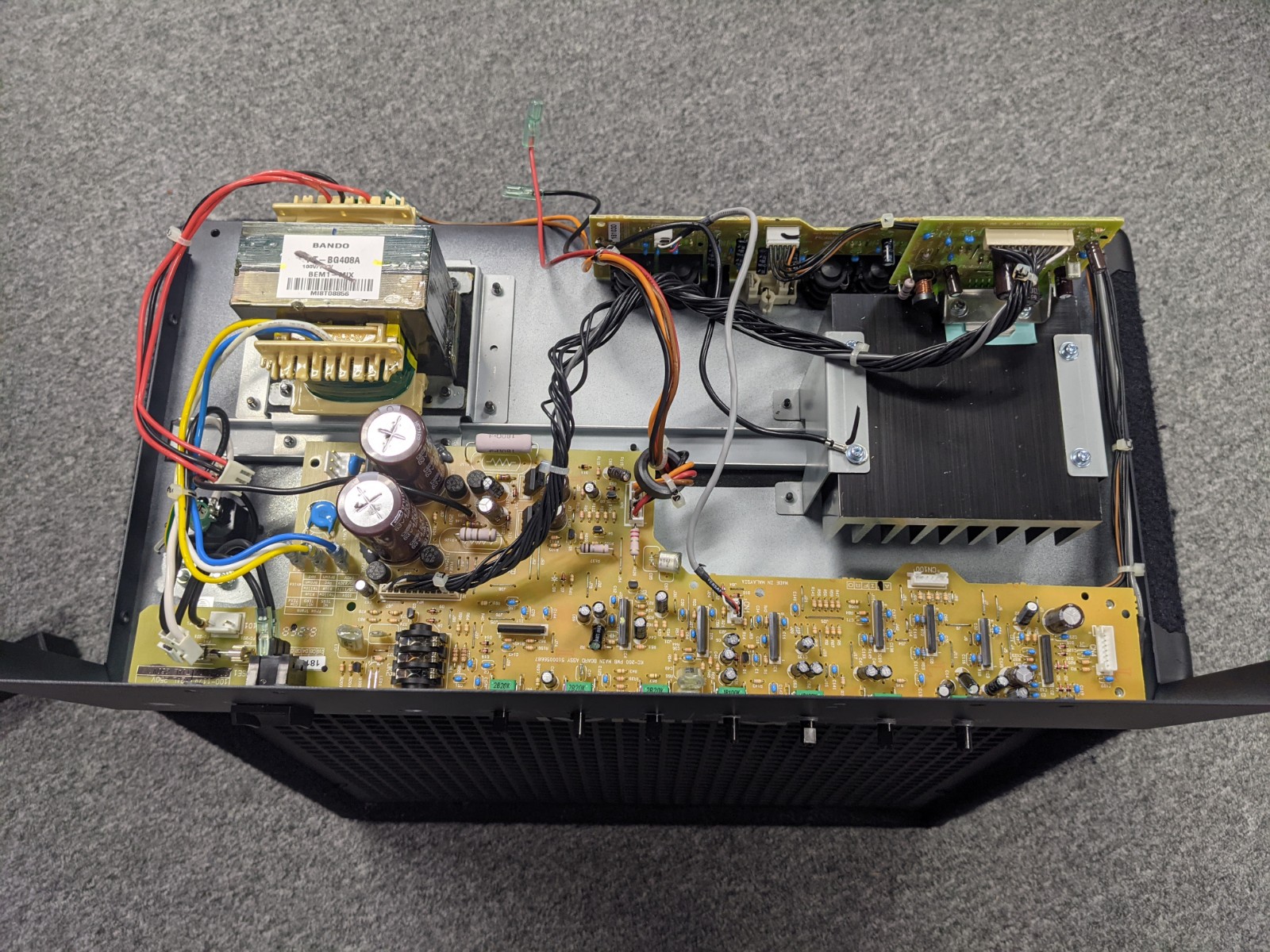
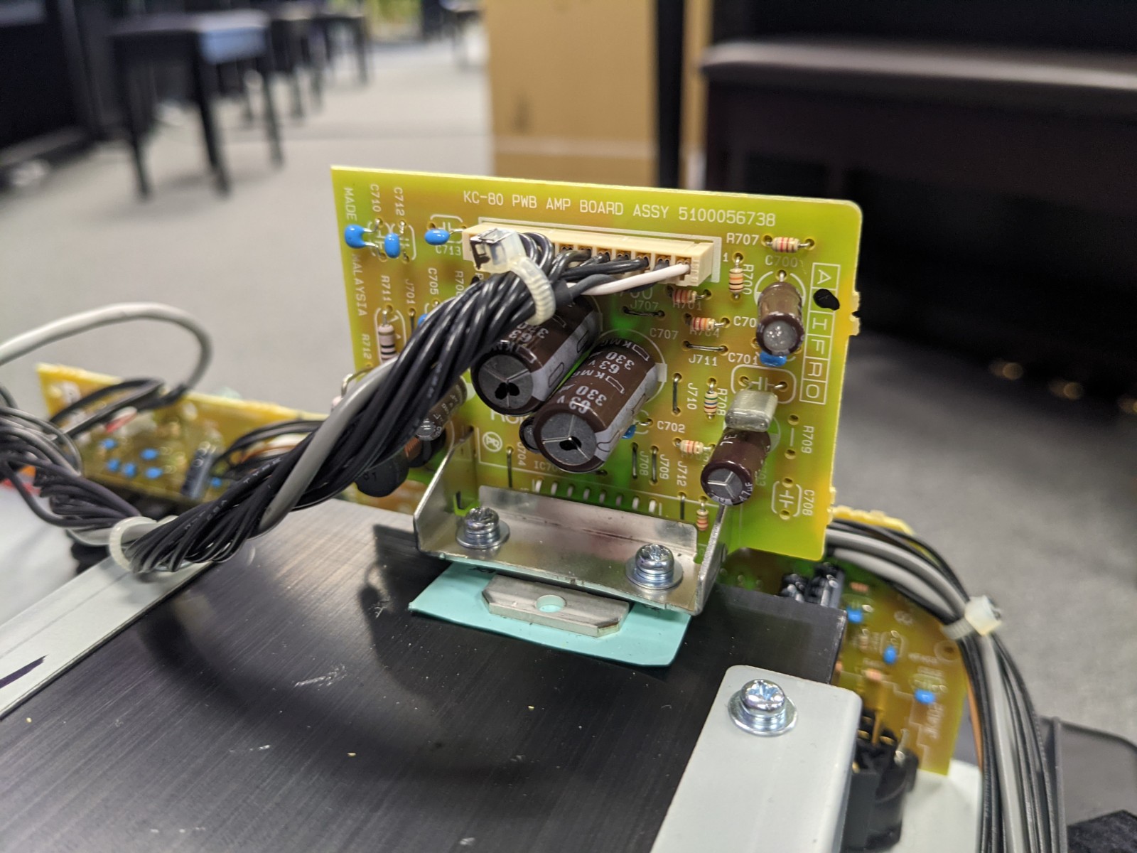
Once all of the settings and connections are properly checked, then we start tearing down the amplifier. Always be careful and drain the main power capacitors. I can’t tell you how many times I have heard of people getting shocked without the amplifier even being plugged in. Always drain the power capacitors before proceeding. After the caps have been drained, the first components you always check are the fuses. This amplifier has (5) fuses on the main power rails. An easy way to check to see if the fuses are still good is the check continuity across the fuse. If there is no continuity then they are presumed to have been tripped and they no longer allow current to flow through them. This is different from resettable fuses and electric circuit breaker ICs.
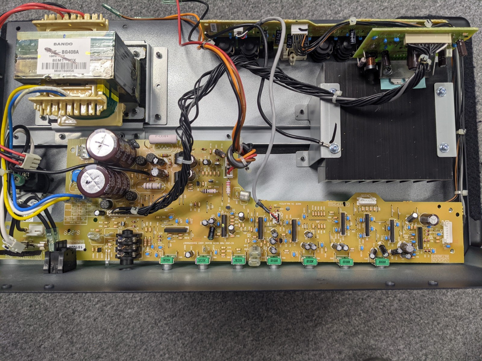
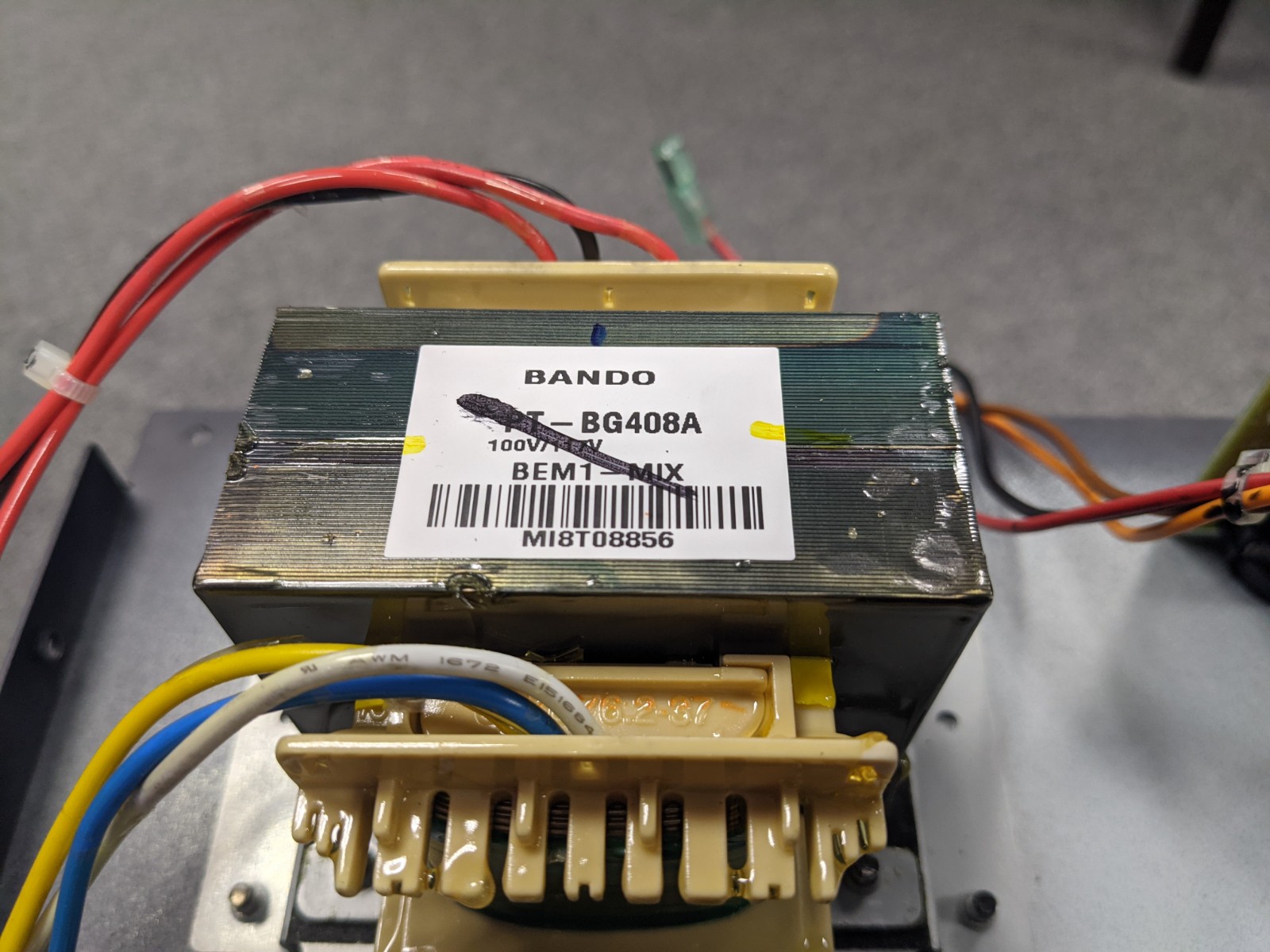
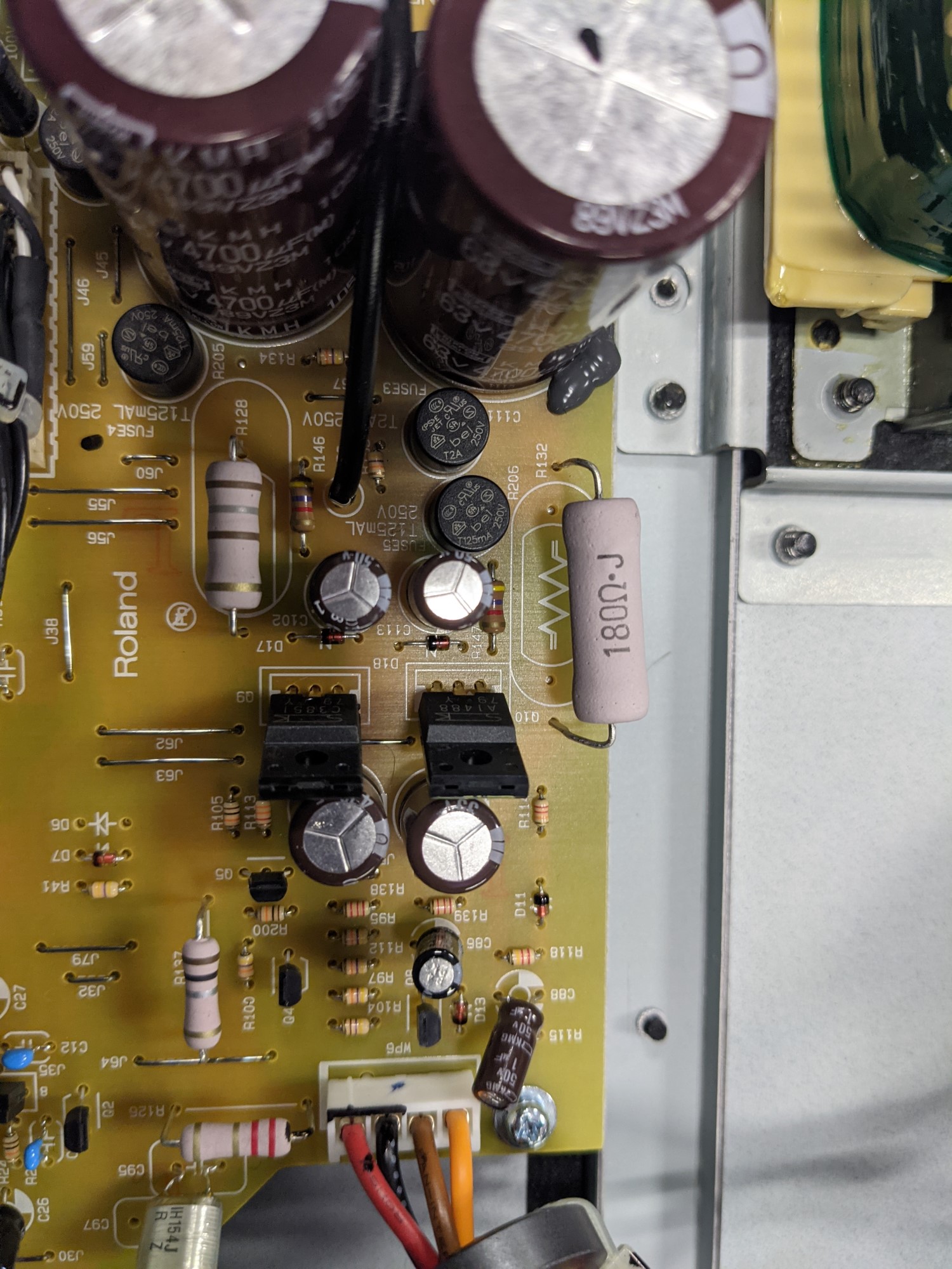
Once the fuses were verified to be working properly the next task is to check the power rails themselves. In the schematic the voltage for VCC is not listed. So we do some investigating. First thing to look at is the main power capacitors coming off of the rectifier. They are rated for 63VDC and one is placed on the positive rail and the other capacitor is placed on the negative rail. This gives me a clue that the transformer may be wound to have a ratio close to 1:1. Good rectifier capacitors can be costly and manufacturers are general going to try and keep their costs down and not wildly exceed their application constraints. Usually the generally practice is to use capacitors with a max voltage that exceeds the application voltage by around 20% to 30%. Some applications you would use 10% to 15% but for rectifier voltages coming from mains power, you need some extra headroom. So if we look at Hammond Manufacturing’s design guide for rectifier use http://www.hammondmfg.com/pdf/5c007.pdf , we can see that the average DC voltage coming from the rectifier is roughly 90% of the AC supply. So if we take 110VACrms and multiply that voltage by 0.9, we get 99VDC for the average. Now let us divide that voltage by 2 because the amplifier is using a virtual ground that is split evenly between two resistors. This would give us voltages around +/-49.5VDC. This is confirmed when we took measurements of VCC. We read +49VDC for the positive rail and -48.5VDC for the negative rail.
Next we shift gears and look at the +/-15VDC rails for the operational amplifiers. These power rails are delivered via linear regulation. Roland uses two power transistors for the +/-15VDC rails. The positive rail uses a npn style bjt transistor and the negative rail uses a pnp style bjt transistor. Figure 1 shows the circuit diagram of this configuration. The voltages are regulated by placing zener diodes on the base of each transistor. That regulates the emitter output to VE(Emitter Voltage) = VB(Base Voltage)-VBE(Base to Emitter Voltage). Depending on the transistor characteristics and temperature of the transistor, VBE can vary somewhere around 0.5V or less to over 0.7V. A good rule of thumb is to use a VBE of 0.65V. By looking at the zener diode value we can see that Roland is using a 16.5V +/- 2.5% zener diode. So now if we calculate 16.5V/1.025 – 0.65V, we get 15.45V on the emitter of the transistor. Now that we know the expected values we can measure the +/-15VDC rails. The +15VDC rail was measured at +15.8VDC while the -15VDC rail measured -6VDC and the transistor was becoming extremely hot. Now we have found our problem.
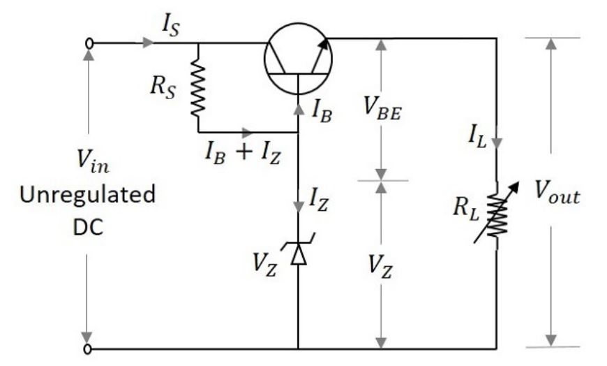
Figure 1. Transistor Linear Regulation Circuit.
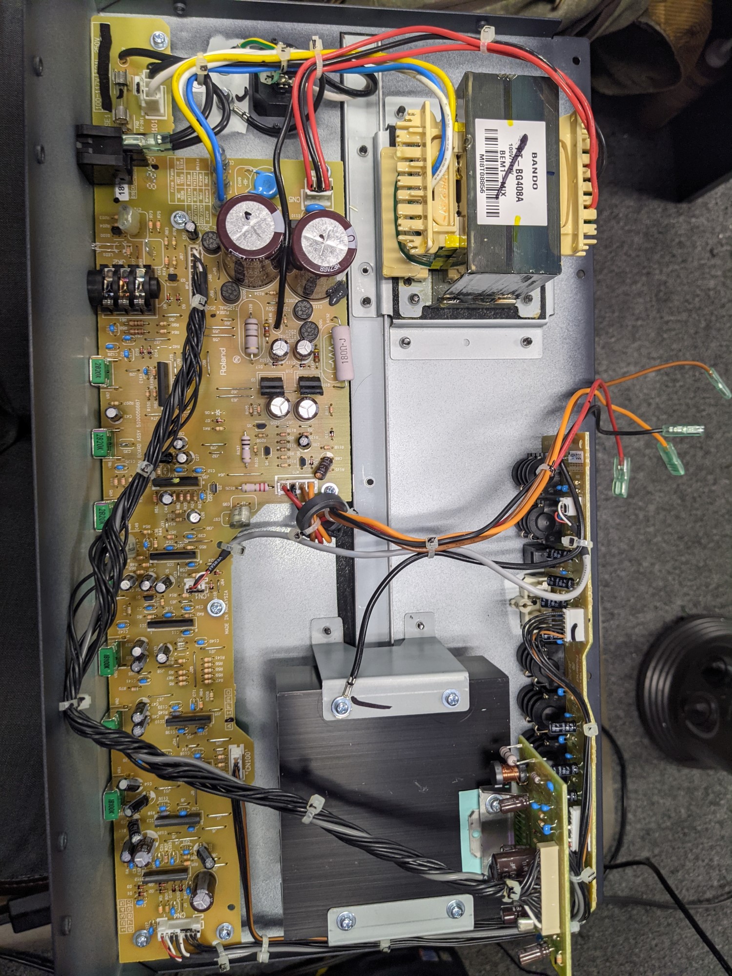
Since the pnp transistor is not properly regulating the output voltage we need to see why. Is there a problem with the transistor? Is there a problem with the zener diode? Is there an issue with the capacitor across the zener diode? Is there an issue on the a passive component on the output of the transistor? Or could it be something as simple as a solder joint? The easiest issue to solve first is look at the solder joint and make sure the leads on the components are actually making good connectivity. After inspection there was no issue with solder joints. Next we need to look at what the transistor. A bjt transistor can be checked by setting your multimeter to diode mode and checking across the different elements. The transistor checked fine. There must be something going on with one of the passive output components. The first logical place to look is the 470uF output capacitor. By removing one leg of the capacitor from the circuit we can see if the capacitor’s ESR is essentially causing a short to our virtual ground. Bingo, the output capacitor was the issue. After replacing the output capacitor we started seeing -15.9VDC on the emitter of the pnp transistor. The transistor was also replaced because of the thermal damage that the short might have caused.
After installing the new pnp transistor and the new output capacitor, the keyboard amplifier now works properly. By using circuit theory to calculate what the voltages should be and methodically testing each component to verify the calculations, one can easily find the solution to various issues within a circuit. If you find this story interesting let us know, and if you have an amplifier of your own that hasn’t been working properly, then give us a shout.
Roland KC-200 Keyboard Amp Repair
Fill out the form below or visit our Contact Page. We would love to hear from you!
We are MITA certified.
![]()


