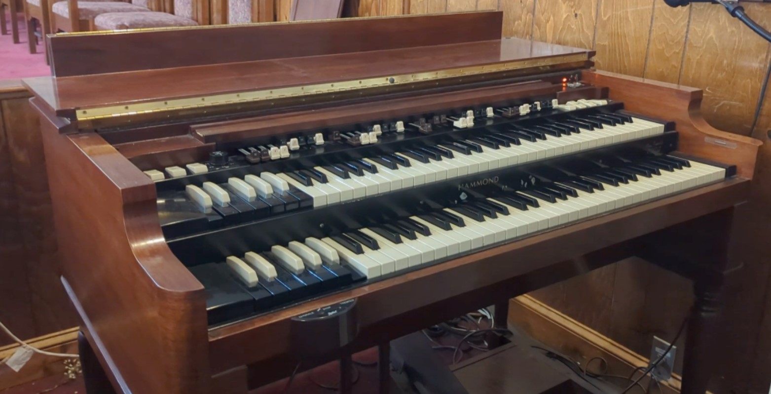
The Leslie Speaker produces one of the most coveted sounds among organists. Nothing sounds quite like the horn cutting through the mix with that perfect spin in chorale or tremolo. Along with bass thumping to just the right speed. With most mechanical and electrical items age becomes a factor and your Leslie might not work to the best of its abilities. In this article I am going to discuss how an Organ interacts with a Leslie to control the motors from chorale to tremolo. In this explanation I will be demonstrating how the Leslie interacts with a VINTAGE HAMMOND B3. Now of course a Leslie can hook up to a ton of different instrument but for simplicity I will only be discussing the hookup arrangement for this particular organ. As my grandparents would say “there is more than one way to skin a cat”, in this discussion we will neither be skinning or explaining any other ways the setup a Leslie at this time.
The Leslie 122
The Leslie 122 is one of the most iconic speakers of all time. All though it is around 40W it packs a punch. Below I have attached a picture of the switching scheme.

Fig. Leslie Switching Circuit for a 122.
Let’s go a little in depth on how the whole system works. First off the Hammond B3 needs a way to connect to the Leslie 122. That is achieved with the addition of a Leslie 122 Kit. The Leslie 122 Kit comes in different forms but in this discussion we will be using the 8000 kit. There are two main versions of the kit.
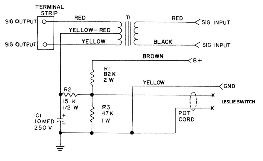
Fig. Fish Organs documentation on 8000 Leslie Hookup Kit with Transformer. Here is a link to the Fish Organ 8000 Leslie Hookup Kit webpage.
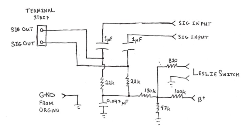
Fig. Rough Sketch of a 8000 Leslie Hookup Kit Using Capacitors.
There are eight connections to the 8000 kit. The signal input comes from both G terminals of the organ pre-amplifier along with a ground connection that is usually tied to the chassis of the amp. Next we have two wires going to the Leslie switch. The last three connections are the signal outputs and the B+ voltage supply. The B+ is either supplied from the 122 Leslie on pin 5 of a 6 pin Leslie cable or from a resistor coming off the rectifier of the organ pre-amp. B+ can be up to a few hundred volts and only professionals in the field should work around that type of voltage. If you do not know what you are doing, that voltage can cause serious injuries or worse. So again this is just a reference document not an installation document.
The 8000 kit is a pretty simplistic and clever design in the way it blocks DC voltage from interacting with the organ itself. In the transformer version the secondary and the primary are galvanically isolated which completely separates both sides from interacting with one another except through magnetism. This is great because we need around 60VDC to travel to the Leslie 122 and not back to the organ. The capacitor version achieves the same goal. The capacitors work just like the transformers in this instance by blocking DC Voltage but allowing AC voltage to pass freely (at least at the certain frequencies the organ produces).
Okay, so we have our B+ voltage running through the 8000 kit and it is supplying about 60VDC to the signal outputs of the kit. How does the Leslie switch interact with this kit? The Leslie switch only has two positions, open or close. Yes, I know some organs have a stop feature that includes a three position Leslie switch, but we are only talking about chorale and tremolo in this article. When the Leslie switch is set to chorale the switch is said to be in the open position. This means that the contacts of the switch are physically not making contacting with one another. This produces 60VDC on the signal outputs. When the switch goes into tremolo position the switch is said to be closed. That is when the contacts of the switch physically make contact with one another. This grounds the B+ voltage through the 8000 kit. In the transformer version this is through the 82k resistor and in the capacitor version this is through the 100k resistor. When the B+ voltage is grounded then this removes the DC voltage from the signal output of the 8000 kit. I know the switch has some resistance and you still may have some DC voltage on the signal output. For simplicity I am saying 0 DC Voltage. The most important thing is that it drops the DC voltage on the signal output below the switching voltage threshold.
Below is what a 4VPP sinewave at 1kHz looks like with no DC voltage and then a picture of a the same sinewave with 60V DC voltage offset.
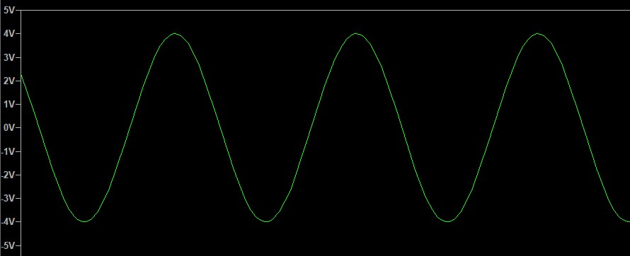
Fig. Signal output with no DC Voltage applied.
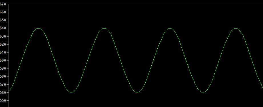
Fig. Signal output with DC Voltage applied.
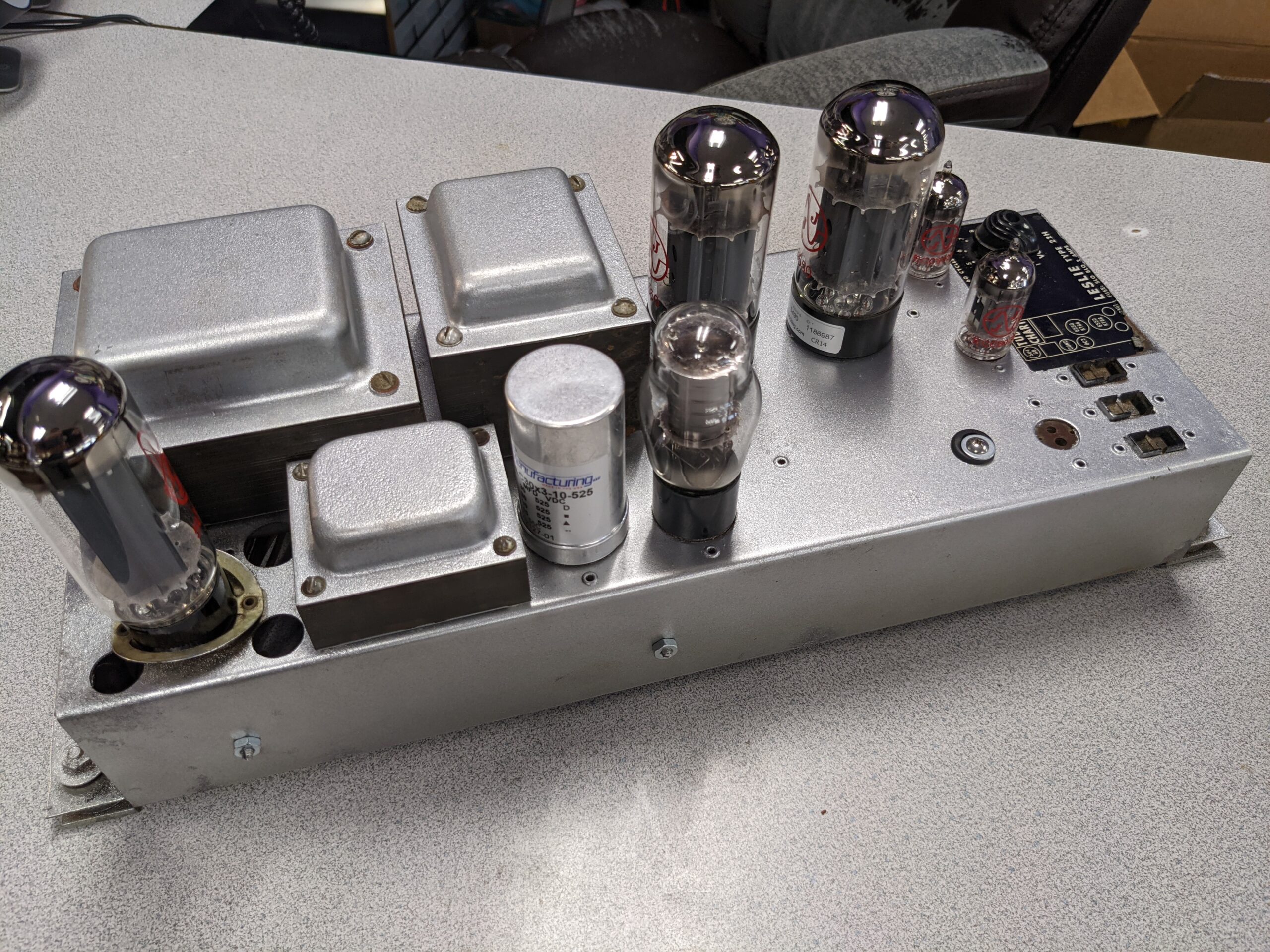
Okay now we have our 8000 kit setup and we are passing the output signals to the Leslie 122 amplifier. What happens inside the Leslie 122 amp? Below is a schematic of a Vintage Leslie 122.
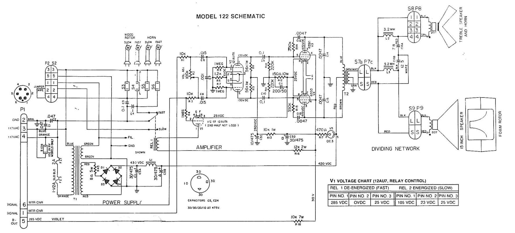
Fig. Vintage Leslie 122 Schematic.
Let’s take a quick peek at the Leslie 122 schematic. The switching tube is right in the middle of the schematic. It is called V1 and it is a 12AU7 tube. The switching scheme only uses 1/2 of the tube. This tube uses pin 6 of the Leslie input cable as the relay control signal. The control signal flows throw the 1 MEG resistor tied to pin 2 of V1 (the 12AU7 switching tube). Pin 1 of V1 is tied to one side of the relay coil and pin 3 is tied to the 25VDC cathode voltage of the 6550 output tubes V3 and V4. Vacuum tubes in general are voltage controlled devices. A voltage gets applied to the grid allowing current to flow between the anode (also known as the plate) and the cathode. If a positive voltage is applied to the cathode of a tube then that affects the reference point of the tube. For example, let’s take the 122 amplifier schematic shown above. If we apply the 25VDC to the 12AU7 switching tube’s cathode like it is shown above and we apply 0VDC at the grid, the tubes reference point will be 25VDC higher than the input at the grid. This is because the grid is essentially 25V less than the cathode. This will stop the flow of electrons from the anode and the cathode (pin 1 and pin 3 in this example). Now let’s apply a voltage of around 25V to the grid. The tube in this instance will start to allow electrons to flow between the anode and the cathode. When using this principle you can create a switch using a tube.
Alright, now we know how the tube works. So now what? When the tube allows electrons to flow the relay becomes energized. This allows the electrons in the coil of the relay to flow through the tube and across the 150 Ohm resistor going to ground. The electrons flowing through the coil creates a magnetic field causing the switch in the relay to close on another contact. Then when 0VDC is applied to the grid of the switching tube the flow of electrons stop and the relay’s magnetic field dissipates and the relay switches back to the starting contact which is called the relays nominal state. Now we can control two states.
We are finally at the end. Now that we can control two different states, we can control two different motors. The relay used in a 122 has five connections: a common, nominal contact, switched contact, and two relay connections. The common input is connected to Pin 4 of the 6 Pin Leslie Connector. This supplies the 117VAC that is needed for the motors. The nominal contact is connected to the fast AC terminal S4 and S6 on the schematic. The switched contact connects to the slow AC terminals S3 and S5. There is also a jumper in between the relay and the slow AC terminals allowing for a stop position also known as the brake. We are leaving this jumper connected for our purposes. The relay coil has two connections one goes to the anode of the switching tube V1 and the other end is connected to a 12k resistor. The 12k resistor supplies the current that will flow through the coil of the relay.
Okay, the switching scheme is all set to go now we connect our motors. In a Leslie 122 we have 4 different motors. The newer Leslie’s like the 122A and 122XB only have two motors, but we are looking at the old school ones. Below is a picture of the top motors. The bottom motors have the same setup except the motor positions are swapped.
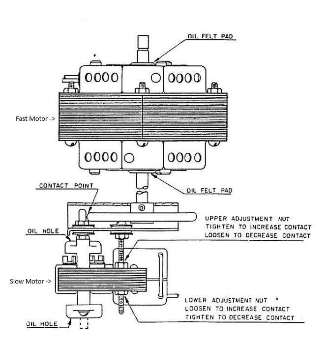
Fig. Leslie Top Motors.
Once the both fast motors and both slow motors are connected you will be able to switch between fast and slow speeds.
Now there are several things that can cause your Leslie to not switch speeds or not spin at all. I am hoping to create another page that I can link to later explaining some servicing tips to troubleshoot Leslie issues but until then just message me and I will see if I can help. Contact me below if you would like to get your Leslie fixed. Also, if you find this article interesting leave me a message or if you find something I got wrong shoot me a message as well, I would love to hear from you. Thanks so much for reading the post.
Leslie 122 Questions
Fill out the form below or visit our Contact Page. We would love to hear from you!